AIM: To Study and Verify the Truth Table of Logic Gates.
LEARNING OBJECTIVE: Identify various ICs and their specification.
COMPONENTS REQUIRED:
- Logic gates (IC) trainer kit.
- Connecting patch chords.
- IC
- IC 7404 NOT GATE
- IC 7408 AND GATE
- IC 7432 OR GATE
- IC 7400 NAND GATE
- IC 7486 XOR GATE
- IC 7402 NOR GATE
- IC 74266 XNOR GATE
THEORY:
The basic logic gates are the building blocks of more complex logic circuits. These logic gates perform the basic Boolean functions, such as AND, OR, NAND, NOR, Inversion, Exclusive-OR, Exclusive-NOR. Fig. below shows the circuit symbol, Boolean function, and truth. It is seen from the Fig that each gate has one or two binary inputs, A and B, and one binary output, C. The small circle on the output of the circuit symbols designates the logic complement. The AND, OR, NAND, and NOR gates can be extended to have more than two inputs. A gate can be extended to have multiple inputs if the binary operation it represents is commutative and associative.
The different types of logic gates are:
NOT Gate
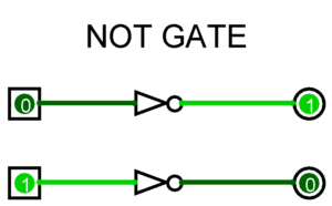
The inverter is a logic gate which has only one input & one output. In inverter is Always opposite of input.
which means if set input LOW is output HIGH.if set input HIGH is output is LOW. the output is given below.
Logic equation is: X = X Digital IC for NOT: IC 7404.
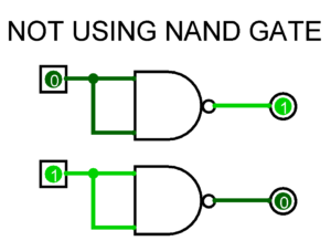
IC: 7404 NOT GATE USING UNIVERSAL GATES
AND Gate
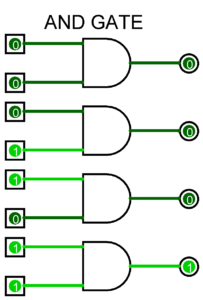
AND gate is a logic gate Which can have two or more inputs.But there is only one output.
The output of AND gate is high only if all inputs are HIGH .
Even if one input is LOW the output is LOW. the output is given below.
Logic equation is: X = A . B Digital IC for AND: IC 7408.
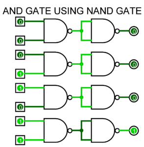
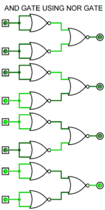
IC:7408 AND GATE USING UNIVERSAL GATES
OR Gate
OR gate is a logic gate Which can have two or more inputs.But there is only one output.
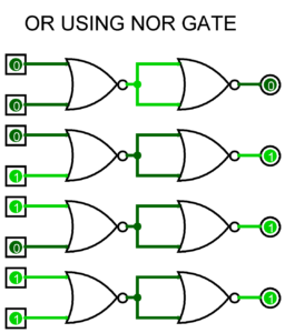
The output of OR gate is HIGH only if a one of the inputs are HIGH Even if one input is LOW, the output will HIGH. Only when both of input is zero the output will also LOW. the output is given below.
Logic equation is: X = A + B Digital IC for OR: IC 7432.
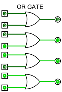
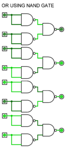
IC: 7432 OR GATE USING UNIVERSAL GATES
NAND Gate
NAND gate is a logic gate Which can have two or more inputs.But there is only one output.
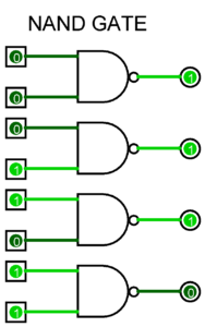
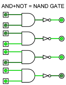
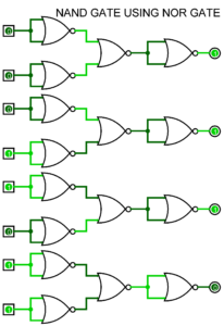
NAND is Compliment of AND .The output of NAND gate is HIGH only if one inputs are HIGH or both input being LOW.if both input is HIGH the output is LOW, the output is given below.
Logic equation is: X = A . B Digital IC for NAND: IC 7400.
| TRUTH TABLE | |||
|---|---|---|---|
| INPUT | OUTPUT | ||
| A | B | X = A . B | DIAGRAM |
| 0 | 0 | 1 | |
| 0 | 1 | 1 | |
| 1 | 0 | 1 | |
| 1 | 1 | 0 | |
IC: 7400 NAND GATE USING UNIVERSAL GATES
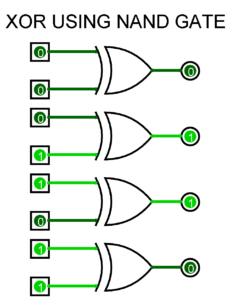
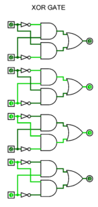
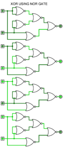
XOR Gate
XOR gate is a logic gate Which can have two or more inputs.But there is only one output.
The output of XOR gate is HIGH only if one of the inputs are HIGH.
if both input is same the output is LOW, the output will below.
Logic equation is:X = A ⊕ B Digital IC for XOR: IC 7486.
IC: 7486 XOR GATE USING UNIVERSAL GATES
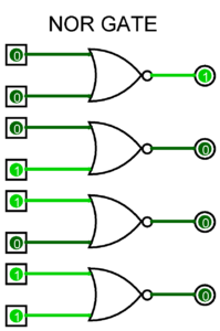
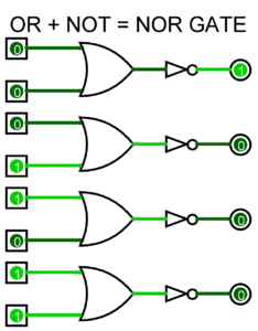
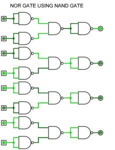
NOR Gate
NOR gate is a logic gate Which can have two or more inputs.But there is only one output.
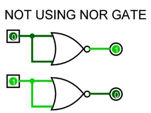
NOR Gate is Compliment of OR. The output of NOR gate is HIGH only if both inputs are LOW.if Any input is HIGH the output is LOW, the output is given below.
Logic equation is: X = A + B Digital IC for NOR: IC 7402.
IC: 7402 NOR GATE USING UNIVERSAL GATES
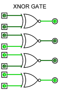
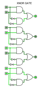
XNOR Gate
XNOR gate is a logic gate. Which can have two or more inputs.But there is only one output.
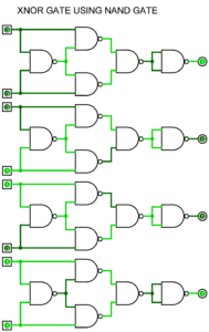
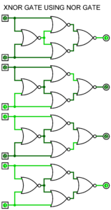
XNOR Is Compliment of XOR . The output of NAND gate is HIGH only if Both inputs are same.
if both input is different the output is LOW, the output will below.
Logic equation is:X = A ⊕ B Digital IC for XNOR : IC: 74266.
IC: 74266 XNOR GATE USING UNIVERSAL GATES
| XNOR | XNOR GATE USING NAND GATE | XNOR GATE USING NOR GATE |
|---|---|---|
Designing and Simulating Digital Logic Circuits
good Job!
Thanks you
kayu gaam bhai?
Hi there just wanted to give you a quick heads up. The words in your content seem to be running off the screen in Opera. I’m not sure if this is a format issue or something to do with internet browser compatibility but I figured I’d post to let you know. The design look great though! Hope you get the issue solved soon. Cheers
It may be due to not updated of Opera Browser. im download and check in Opera Browser it is work fine.
Thanks for Supporting us.
we are trying to make our Ranking best positions.
I can’t believe how great this site is. You keep up the good work. That’s my advice pal.
Just fabulous. Who wrote this and how can we get more?
I really can’t believe how great this site is. Keep up the good work. I’m going to tell all my friends about this place.
This site looks better and better every time I visit it. What have you done with this place to make it so amazing?!
tSkUJecZLmDoMQy
Thanks for writing wonderful Content